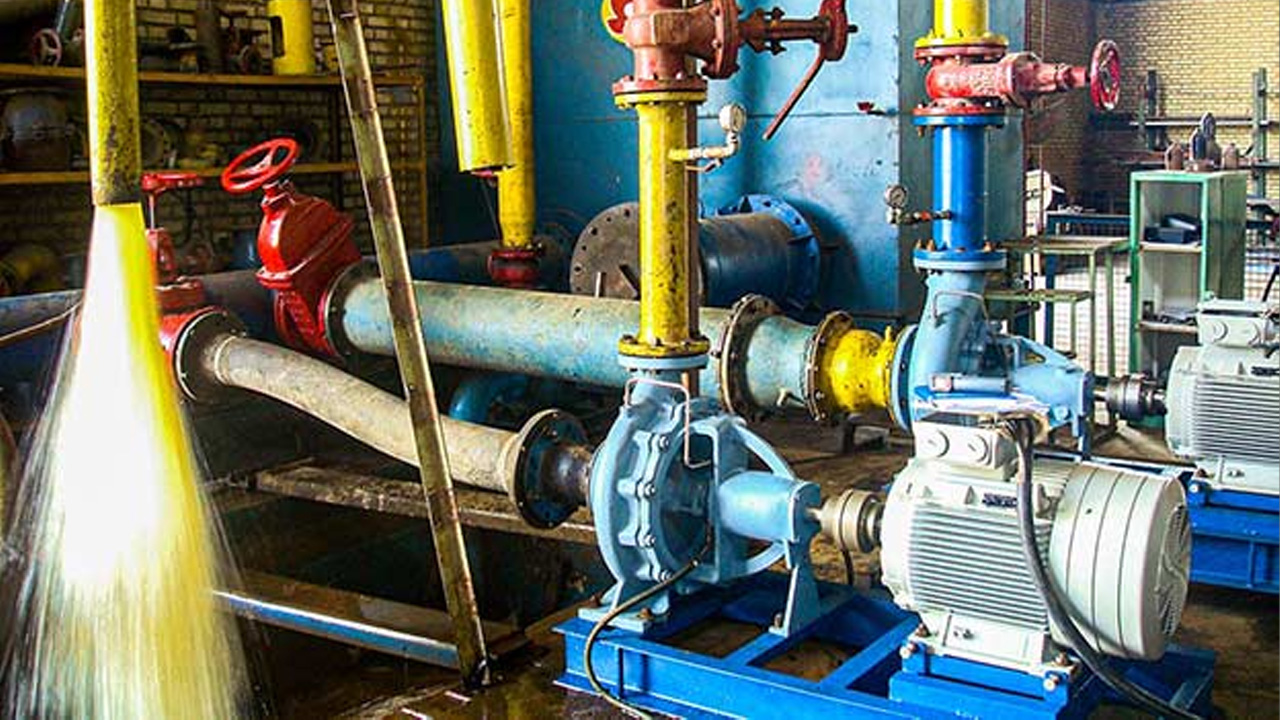
Water Leak Detection System
Water Leak Detection System
The cable sensors are typically used to detect water leaks usually under floors, and are used in conjunction with the detection modules which are connected to control panel. The cable excitation used is an isolated AC signal which ensures the detectors will not be subject to oxidation or erosion over time, avoiding the degradation problems associated with DC systems.
Different technologies to extinguish fire depending on the occupancy and type of fire is as follows.
Standards Followed
The Indian Standards (IS) for fire safety and gas suppression systems are established by the Bureau of Indian Standards (BIS) to ensure the safety and reliability of fire protection mechanisms. These standards cover various aspects, including design, installation, maintenance, and performance of fire suppression systems. IS 15105:2002 is a key standard related to gas-based fire suppression, ensuring compliance with safety protocols in commercial and industrial applications.
The National Building Code (NBC) of India provides comprehensive guidelines for fire safety, including fire suppression systems. It categorizes buildings based on occupancy and prescribes the necessary fire protection measures. Part 4 of the NBC specifically addresses fire and life safety, recommending gas suppression systems for areas where water-based suppression is unsuitable, such as data centers and electrical rooms.
The National Fire Protection Association (NFPA) is a globally recognized organization that develops fire safety standards, including those for gas suppression systems. NFPA 2001 is a crucial standard governing clean agent fire suppression systems, ensuring effective fire control without damaging sensitive equipment. NFPA standards are widely adopted for their rigorous safety and performance requirements.
The British Standards (BS) set by the British Standards Institution (BSI) provide fire protection guidelines widely used in the UK and internationally. BS EN 15004 is a significant standard covering gaseous fire suppression systems, aligning with international best practices. These standards ensure that suppression systems meet high safety, reliability, and environmental impact criteria.
FM Global (Factory Mutual) and UL (Underwriters Laboratories) are independent organizations that certify fire suppression systems for quality, reliability, and effectiveness. FM-approved and UL-listed gas suppression systems meet stringent testing criteria, ensuring they function efficiently in real-world fire scenarios. Compliance with these certifications assures businesses and industries of the highest safety and performance standards.
Service Industry
- Commercial
- Residential
- Institutional
- Assembly
- Business
- Hospital
- Educational
- Industrial
- Mercantile
The above inclusive of the Office building ,Shopping centers, Mall, Auditorium, Banks, Hotels, Residences, Laboratories, Hospitals, Colleges, Dormitory blocks, Factories, Ware houses, Server room, Electrical equipment blocks.
Flow Calculations
Flow calculations are fundamental in hydraulic systems, as they determine the movement of fluids through pipes, channels, and other conduits. The continuity equation (Q=A×VQ = A \times VQ=A×V) ensures mass conservation, where QQQ is the flow rate, AAA is the cross-sectional area, and VVV is the velocity. Bernoulli’s equation, which accounts for pressure, velocity, and elevation, helps analyze energy conservation in a fluid system. Additionally, Reynolds number (ReReRe) determines whether the flow is laminar, transitional, or turbulent, which influences design considerations.
Flow Calculations

Pressure Loss Calculations

Pressure Loss Calculations
Pressure loss occurs due to friction and turbulence as fluid moves through pipes and fittings. The Darcy-Weisbach equation is commonly used to calculate friction losses, incorporating pipe length, diameter, velocity, and a friction factor. For water distribution systems, the Hazen-Williams equation is often preferred due to its simplicity. Besides frictional losses, minor losses occur due to fittings, valves, bends, and sudden expansions or contractions in the pipeline, which must be accounted for in system design.
Pump and System Head Calculations
Pumps are used to overcome system head losses and deliver fluids at the required pressure and flow rate. The total dynamic head (TDH) consists of static head (elevation difference), friction losses, and velocity head. Pumps must also consider Net Positive Suction Head (NPSH) to avoid cavitation, which can damage the impeller. The affinity laws help predict pump performance under different operating conditions, allowing engineers to scale pump efficiency as needed.
Pump and System Head Calculations

Pipe Sizing Calculations

Pipe Sizing Calculations
Proper pipe sizing ensures optimal flow rates while minimizing energy losses and excessive pressures. The selection is based on velocity limits, pressure drop constraints, and pipe material. The Colebrook equation and Moody chart help determine the friction factor, essential for calculating pressure loss in turbulent flow conditions. In practice, engineers aim for an economical balance between larger pipes (lower velocity, less friction) and smaller pipes (higher velocity, more friction).
Hydraulic Radius and Open Channel Flow
In open channel flow, where a free surface is exposed to atmospheric pressure, the hydraulic radius (R=A/PR = A / PR=A/P) is a key parameter, where AAA is the flow area and PPP is the wetted perimeter. Manning’s equation is widely used for flow velocity prediction in natural and man-made channels. The slope of the channel, surface roughness, and hydraulic radius all influence the efficiency of water transport, impacting drainage, irrigation, and river engineering projects.
Hydraulic Radius and Open Channel Flow

Sprinkler and Fire Protection Hydraulic Calculations

Sprinkler and Fire Protection Hydraulic Calculations
Fire protection systems rely on hydraulic calculations to ensure adequate water supply and pressure for sprinklers and hydrants. The K-factor equation (Q=K×P0.5Q = K \times P^{0.5}Q=K×P0.5) relates the flow rate to the orifice size and operating pressure of a sprinkler. Engineers must also consider available water supply, pipe friction losses, and the layout of sprinkler networks to ensure proper system performance in emergency conditions.
Stormwater and Drainage Calculations
Stormwater management systems are designed to handle runoff from rainfall events. The Rational Method (Q=CiAQ = CiAQ=CiA) estimates peak discharge based on rainfall intensity (iii), runoff coefficient (CCC), and drainage area (AAA). Time of concentration, which represents the time for runoff to travel to an outlet, influences drainage design. Proper hydraulic calculations ensure flood prevention, erosion control, and efficient stormwater conveyance.
Stormwater and Drainage Calculations

Hydraulic Structures Calculations

Hydraulic Structures Calculations
Hydraulic structures such as weirs, spillways, and culverts regulate water flow in rivers, reservoirs, and dams. Weir flow equations determine discharge over structures, while orifice flow calculations help size openings for controlled flow rates. Spillway design must account for extreme flood events, ensuring safe water discharge without structural failure. These calculations play a crucial role in water resource management and infrastructure resilience.
Scope of our Work:
- Preliminary site visit and discussion with Architect / Client and project feasibility survey.
- Necessary NOC drawings with document (No objection certificate). (For base building projects).
- Preparation of Preliminary design Brief (DBR) with Schematic.
- Preparation of Preliminary designs for the Client / Architects approval of comments if any, by way of drawings to explain the general planning and nature of works with the basic dimensions, inclusive of basic requirement for the safety & security systems shafts etc and other features required for services. Obtaining the approval of the Client / Architect.
- Making Technical specification, Bill of Quantity & Tender Layout (For better understanding of our requirement).
- Provided the Estimated Bill of quantity for client to get idea for budgeting.
- Preparing & floating the tender enquiry with tender drawing for system.
- Scrutinizing & comparing the offers of various bidders.
- Providing assistance to client in negotiation and finalizing of the contractors.
- Coordinating the overall designing with other services i.e. HVAC, ELECTRICAL, FIRE FIGHTING & LOW CURRENT systems and preparing the detail section which will be useful for Vendor & PMC to run the project in smooth way and without any issues of installation on site.
- Our support will extend unto preparation of the above false ceiling coordination & False ceiling coordination layouts.
- Describe the requirement of our system to the vendor in the kick off meeting with the Good for construction layout (GFC).
- Checking and approving the shop layout submitted by the vendors.
- Periodical visits to the site of work during the execution to ensure that the intent of the drawings is duly carried out and that technical features envisaged by the consultant are properly executed.
- Generate the site visit report with proper snap shots to reduce the uncertainty of installation. This will help to avoid rework during the commissioning stage.
- Provide necessary test certificate format and witnessing the performance test for all the involved systems.
- We ensure to obtain ideal Handing over procedure.


